

Both the clamp body and the insert are made of stainless steel. In Figure 1, D is the effective inside diameter with the insert seated before crimping, and A is the initial inside ear width. Refer to the part drawing for material grades and dimensional tolerances.
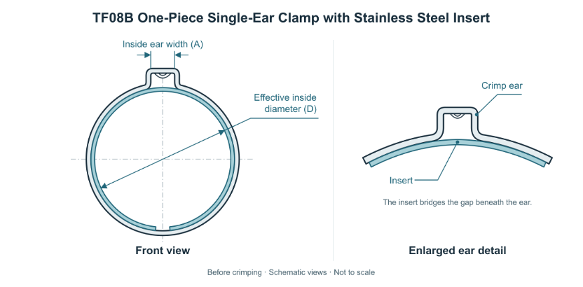 Figure 1 Pre-Crimp Geometry and Insert Detail
Seat the hose on the fitting and measure its outside diameter at the clamping location before crimping. Use the assembly diameter limits and the size ranges in the table to shortlist parts. Then use effective inside diameter D, with the insert seated, to check slide-on clearance and confirm access for the pincer jaws.
Slide the clamp onto the hose before inserting the fitting, then position the clamp in the specified clamping zone. Before crimping, check that the band sits squarely, the insert is seated inside the band and bridges the gap beneath the ear, and the edges are free of burrs that could damage the hose.
Align the matched pincer jaws at the base of the ear and crimp in one stroke at the validated closing force. Closing force is measured in newtons (N). Establish the setting using the band and insert dimensions, hose hardness and wall thickness, fitting support and target compression. Validate the setting on the actual assembly.
Inspect clamp position, ear formation and hose condition. Check the visible portions of the insert for displacement, lifting or curling. Verify installed dimensions or the residual ear gap against the approved acceptance criteria. Before production, trial-fit assemblies at both outside diameter limits and verify leak tightness or axial pull-off resistance as required by the application.
Ear formation provides a visual check. If an assembly fails inspection, follow the approved rework procedure. Do not re-crimp the same ear.
Specify the TF08B part number, quantity, and assembled hose outside diameter and tolerance. If the application requires a specific effective inside diameter, body or insert material, dimensional tolerance or edge finish, include mating hose and fitting drawings with the inquiry.
The listed sizes span 4.2–30.0 mm across the series. When ordering, verify the size range and initial inside ear width A for the specific Towin part number. Confirm effective inside diameter D and its tolerance on the part drawing.
| Part number | A (mm) Inside ear width |
Size range(mm) | Part number | A (mm) Inside ear width |
Size range(mm) |
| TF08B0001 | 3.2 | 4.2–5.2 | TF08B0022 | 6.5 | 11.8–13.8 |
| TF08B0002 | 3.2 | 4.7–5.7 | TF08B0023 | 6.5 | 12.3–14.3 |
| TF08B0003 | 3.2 | 5.2–6.2 | TF08B0024 | 6.5 | 12.8–14.8 |
| TF08B0004 | 3 | 5.6–6.5 | TF08B0025 | 7 | 13.1–15.3 |
| TF08B0005 | 3.5 | 5.9–7 | TF08B0026 | 8 | 13.2–15.8 |
| TF08B0006 | 4 | 6.3–7.5 | TF08B0027 | 7 | 13.9–16.1 |
| TF08B0007 | 4 | 6.6–7.8 | TF08B0028 | 7 | 14.6–16.8 |
| TF08B0008 | 4 | 7–8.2 | TF08B0029 | 7 | 15.6–17.8 |
| TF08B0009 | 5 | 7–8.5 | TF08B0030 | 7.5 | 16.5–18.8 |
| TF08B0010 | 5 | 7.5–9 | TF08B0031 | 7.5 | 17.1–19.3 |
| TF08B0011 | 5 | 8–9.5 | TF08B0032 | 9 | 17.1–20 |
| TF08B0012 | 5 | 8.5–10 | TF08B0033 | 7.5 | 18–20.3 |
| TF08B0013 | 5.5 | 8.8–10.5 | TF08B0034 | 7.5 | 18.8–21.1 |
| TF08B0014 | 5.5 | 9.1–10.8 | TF08B0035 | 8.5 | 19.2–21.8 |
| TF08B0015 | 5.5 | 9.6–11.3 | TF08B0036 | 8.5 | 20.2–22.8 |
| TF08B0016 | 6.5 | 9.5–11.5 | TF08B0037 | 9 | 21–23.8 |
| TF08B0017 | 6.5 | 9.8–11.8 | TF08B0038 | 9 | 22–24.8 |
| TF08B0018 | 6.5 | 10.3–12.3 | TF08B0039 | 8.5 | 23–25.6 |
| TF08B0019 | 6.5 | 10.6–12.6 | TF08B0040 | 9.5 | 23.3–26.3 |
| TF08B0020 | 6.5 | 11.1–13.1 | TF08B0041 | 11 | 26.5–30 |
| TF08B0021 | 6.5 | 11.3–13.3 |