
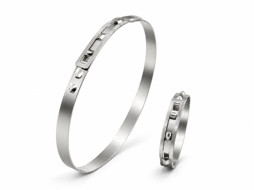
The band tongue seats in a guide groove to reduce the step at the overlap. Once engaged, the load-retaining hook holds the band closed. These designs have a fixed nominal closed size. Verify that the clamp can lock and achieve the required hose compression at both assembly diameter limits.
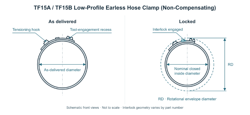 Figure 1 Non-Compensating Clamp As Delivered and Locked
Seat the hose on the fitting. Measure the assembled outside diameter (OD) at the clamping location and establish its limits. Use the as-delivered diameter to check installation access and the nominal closed inside diameter to shortlist parts. Verify actual compression in trial builds, taking hose hardness, wall thickness and fitting support into account.
The compensation corrugation flexes under circumferential band tension to accommodate assembly diameter variation and thermally induced changes within the validated range. Account for both assembly tolerances and temperature changes in service when selecting a clamp.
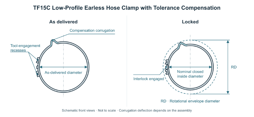 Figure 2 Tolerance-Compensating Clamp As Delivered and Locked
At the minimum assembly OD, verify hose compression and the required sealing or retention. At the maximum OD, confirm full hook engagement and that corrugation deflection stays within the approved limits. Establish the allowable compensation by testing the actual assembly.
Fit the clamp in the direction specified on the part drawing and position it in the designated clamping zone. Seat the matched jaws on the specified tensioning features. Use the validated tool settings to draw the band ends together until the load-retaining hook fully engages. Release the tool and confirm that the hook remains seated.
Check clamp position, hook engagement and the overlap for misalignment or lifting. On TF15C, also check for abnormal corrugation deformation. Verify sealing or axial pull-off resistance on the complete assembly as required by the application.
For rotating assemblies, check the installed rotational envelope diameter (RD) about the actual axis of rotation. Include the interlock and any protruding corrugation, and verify minimum running clearance to adjacent components. On parts approved for reopening, follow the part-specific service procedure and inspect the hooks, recesses and band before refitting. Replace the clamp when required by that procedure.
| Series | Design | Band width × thickness(mm) | Nominal closed ID(mm) |
| TF15A | Non-compensating | 9.0 × 0.5 | 10.5–19.0 |
| TF15B | Non-compensating | 7.0 × 0.6 | 60.0–110.0 |
| TF15C | Tolerance-compensating | 9.0 × 0.6 | 19.5–110.0 |
Specify the Towin part number, quantity, assembly OD limits, required nominal closed inside diameter, installation direction, and operating temperature. Check the as-delivered diameter and nominal closed inside diameter in the table for the selected part number. State any specific material, compensation, installed envelope, or service removal requirements.
For complete data sheets, please refer to the most up-to-date information published on this page (or via the links provided below).
tfurtherclamp.com
TF15B · Non-compensating · 7.0 × 0.6 mm
| Item No. | As-delivered diameter (mm) | Nominal closed ID (mm) |
| TF15B0001 | 64.4 | 60.0 |
| TF15B0002 | 64.9 | 60.5 |
| TF15B0003 | 65.4 | 61.0 |
| TF15B0004 | 65.9 | 61.5 |
| TF15B0005 | 66.4 | 62.0 |
| TF15B0006 | 66.9 | 62.5 |
| TF15B0007 | 67.4 | 63.0 |
| TF15B0008 | 67.9 | 63.5 |
| TF15B0009 | 68.4 | 64.0 |
| TF15B0010 | 68.9 | 64.5 |
| TF15B0011 | 69.4 | 65.0 |
| TF15B0012 | 69.9 | 65.5 |
| TF15B0013 | 70.4 | 66.0 |
| TF15B0014 | 70.9 | 66.5 |
| TF15B0015 | 71.4 | 67.0 |
| TF15B0016 | 71.9 | 67.5 |
| TF15B0017 | 72.4 | 68.0 |
| TF15B0018 | 72.9 | 68.5 |
| TF15B0019 | 73.4 | 69.0 |
TF15C · Tolerance-compensating · 9.0 × 0.6 mm
| Item No. | As-delivered diameter (mm) | Nominal closed ID (mm) |
| TF15C0001 | 22.0 | 19.5 |
| TF15C0002 | 22.5 | 20.0 |
| TF15C0003 | 23.0 | 20.5 |
| TF15C0004 | 23.5 | 21.0 |
| TF15C0005 | 24.0 | 21.5 |
| TF15C0006 | 24.5 | 22.0 |
| TF15C0007 | 25.0 | 22.5 |
| TF15C0008 | 25.5 | 23.0 |
| TF15C0009 | 26.0 | 23.5 |
| TF15C0010 | 26.5 | 24.0 |
| TF15C0011 | 27.0 | 24.5 |
| TF15C0012 | 27.5 | 25.0 |
| TF15C0013 | 28.0 | 25.5 |
| TF15C0014 | 28.5 | 26.0 |
| TF15C0015 | 29.0 | 26.5 |
| TF15C0016 | 29.5 | 27.0 |
| TF15C0017 | 30.0 | 27.5 |
| TF15C0018 | 30.5 | 28.0 |
| TF15C0019 | 31.0 | 28.5 |
| TF15C0020 | 31.5 | 29.0 |
This catalog presents a selection of models and specifications for reference purposes only.