
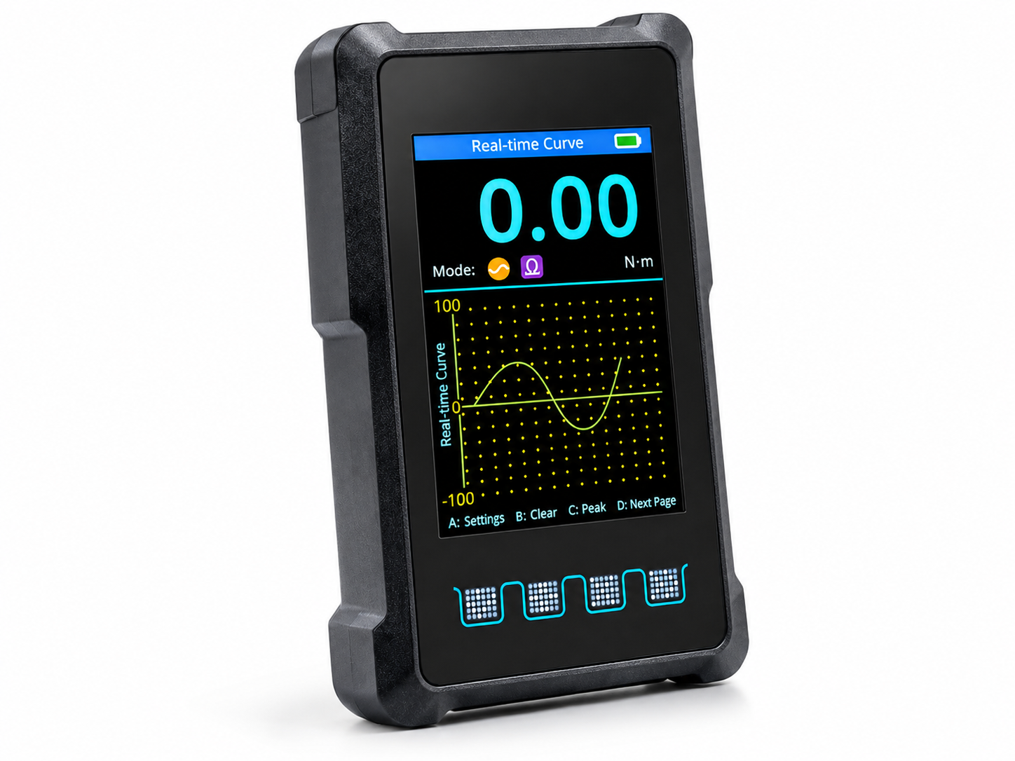
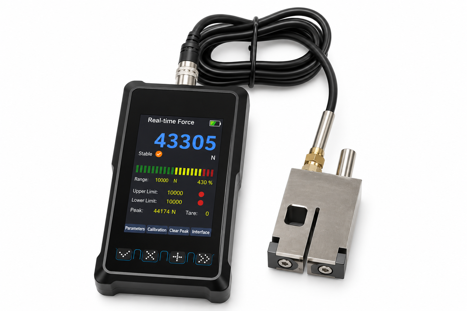
Gauge and Configuration Examples
Built-in and external sensor configurations; live readings and force traces; peak and valley capture with storage for 200 historical sets; selectable sampling rates; USB-C data connectivity and optional RS-485 interface.
| Item | Details |
| Sampling rate | 50, 200, 800, 3,200, 6,400, 12,800 Hz |
| Nonlinearity | < 0.01% |
| Accuracy | < 0.1% |
| Display counts | −99,999 to 999,999 |
| Analog input | −15 to +15 mV |
| Temperature drift | < 20 ppm |
| Battery | 3,200 mAh,Approx. 15 h on a full charge, approx. 1,000 charge cycles |
| Peak and valley history | 200 sets, retained after power-off |
These specifications describe the instrument. Complete measurement system performance also depends on the sensor, fixture, loading method, and calibration status.
The built-in version integrates a sensor for measurements within its rated range. The external version uses a keyed circular connector to connect compatible sensors for different fixtures. Check rated capacity, signal range, wiring, and load direction when selecting a sensor.
| Built-in model | Range | Display increment |
| DY920-1 | −1 to +1 kg | 0.0001 kg |
| DY920-2 | −2 to +2 kg | 0.0001 kg |
| DY920-3 | −3 to +3 kg | 0.0001 kg |
| DY920-5 | −5 to +5 kg | 0.0001 kg |
| DY920-10 | −10 to +10 kg | 0.001 kg |
| DY920-20 | −20 to +20 kg | 0.001 kg |
| DY920-30 | −30 to +30 kg | 0.001 kg |
| DY920-50 | −50 to +50 kg | 0.01 kg |
Ranges and display increments retain the kg notation used in the specification. Display increment denotes the smallest displayed step. For clamp pincer closing force, use N as specified by the process and select a sensor and fixture with suitable capacity.
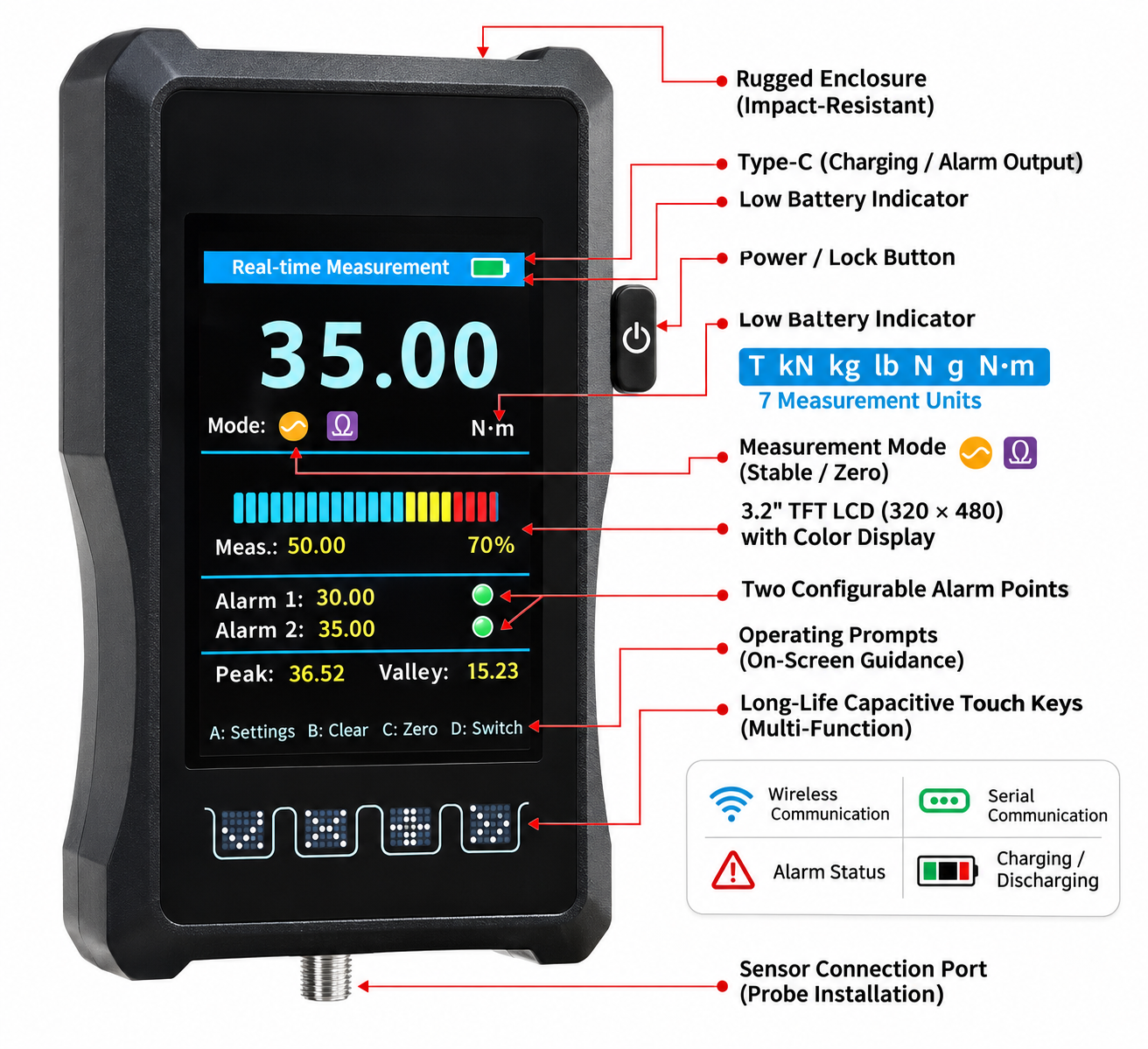 Front Panel and Display
The screen displays live force, units, traces, and operating status. Set the capture start threshold and end condition to complete a measurement by threshold, elapsed time, or keypress. Review the last completed trace and manage live readings and peak/valley history using the selected recording mode.
Secure the sensor and fixture, load in the specified direction, and avoid off-axis loading and impact. With the sensor unloaded, wait for a stable reading and zero the gauge before performing a loading cycle according to the tool and fixture instructions. Record the tool ID, pincer head, settings, unit, and peak force, then evaluate the result against the approved process limits.
The closing-force reading evaluates tool output. It is not a direct measure of the installed clamp’s radial clamping force and does not replace assembly leak, retention, or durability testing.
Connect to a PC using a data-capable USB-C cable or the optional RS-485 interface. Modbus RTU, ASCII, and HEX communications support access to live force and peak/valley values as defined by the protocol. Factory serial settings are 19,200 bit/s, device address 01, and 8N1.
Match the protocol, address, word order, and decimal scaling when integrating the gauge. Power-cycle after changing communication settings. Confirm host software functions and system integration against the selected configuration.
Sensor-parameter setup is supported, with compatible TEDS smart sensors available as an option. When TEDS is enabled, the gauge reads sensor data at startup. Power-cycle after changing sensors and verify range, zero, units, and decimal position.
For quality acceptance, verify the complete measurement system against a valid traceable reference under the applicable metrology procedure. Parameter setup or sensor data retrieval does not replace measurement system verification. Calibration and advanced adjustments should be performed by authorized personnel and documented.
Charge through the USB-C port using a 5 V USB supply. The 3,200 mAh battery provides approximately 15 hours of operation on a full charge. Recharge promptly when the low-battery icon turns red. Switch off and disconnect external devices before cleaning. Wipe with a dry soft cloth and prevent liquids or metal debris from entering the housing.
Specify the built-in or external sensor configuration, capacity, measurement unit, sensor and fixture interfaces, communication requirements, and accessories when ordering. The standard package includes the handheld gauge and a USB-C data cable. Confirm external sensors, connectors, and other accessories against the order configuration.