

The mechanical interlock connects the band ends at the overlap and carries band tension during crimping. As the jaws close the ear, the band diameter decreases and compresses the hose against the fitting.
| Series | Band material | Width × thickness (mm) | Inside ear width (mm) | Series size span (mm) |
| TF13A | 不锈钢 / Stainless steel | 7.0 × 0.6 | 5, 6, 6.5, 7, 9, 10 | 8.9–116.0 |
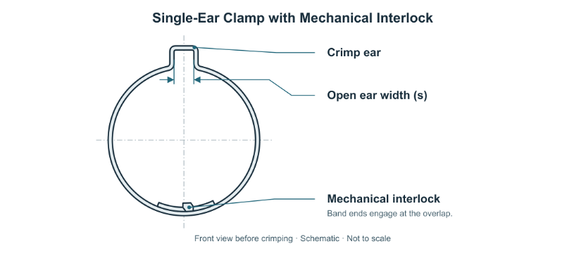 Figure 1 Crimp Ear and Mechanical Interlock Before Crimping
Seat the hose to the specified depth and measure the assembled outside diameter (OD) at the clamping location. Select by the part’s closed-to-open diameter range and inside ear width. Check installation clearance at the maximum OD and verify compression at the minimum OD.
Position the clamp in the specified clamping area. Check that the band sits flat and the interlock is fully engaged. Use a pincer head suited to the selected part number and ear width. Align the jaws at the base of the ear and crimp in a single stroke at the validated closing force.
Closing force is the load the pincer jaws apply to the ear during crimping, measured in newtons (N). Set it using the band dimensions, hose hardness and wall thickness, fitting support and target compression. Validate the setting on the actual assembly. Where the drawing specifies a maximum closing force, use it as the upper limit for the tool.
In Figure 1, s is the inside ear width before crimping. The residual ear gap is the distance between the bases of the ear legs after crimping. Under force control, this gap can vary with assembly size. Check it against the approved process limits and assess it together with measured closing force and assembly inspection results.
Check ear shape, band position and hose surface condition. Verify that the interlock has not lifted, shifted or disengaged under load. Verify sealing or axial pull-off resistance as required by the application. If the assembly falls outside the acceptance limits, follow the approved rework procedure and avoid crimping the same ear again.
For quotations, provide the Towin part number, required diameter range, material or finish, assembly OD limits and quantity. If space around the interlock is limited, include the assembly drawing or available clearance.