
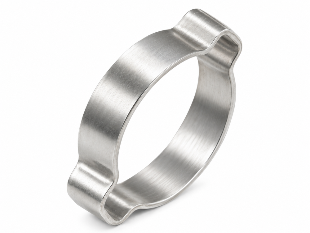
TF14A is made of zinc-plated steel and TF14B of stainless steel. In Figure 1, D is the clamp outside diameter before crimping, B is the band width, T is the band thickness and S is the inside ear width before crimping. Refer to the part drawing for dimensions, tolerances, material grade and coating requirements. Deburred band edges help reduce hose damage during installation.
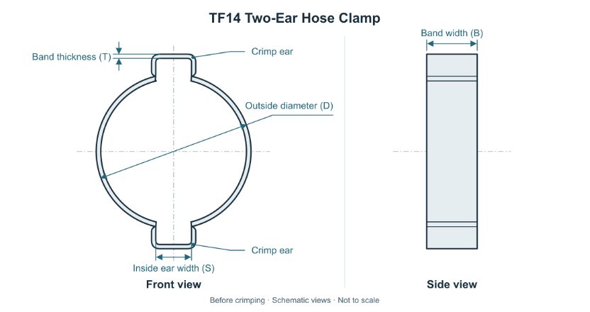 Figure 1 Two-Ear Clamp Geometry Before Crimping
Seat the hose on the fitting and measure its outside diameter at the clamping location. Compare the assembly diameter limits with the clamping range for each candidate part. Then check slide-on clearance, access for inserting and withdrawing the pincer jaws at both ears, and clearance to nearby parts after installation.
Slide the clamp onto the hose before inserting the fitting. Move the clamp into the specified clamping zone, seat the band squarely and ensure the jaws can reach both ears. Align the matched pincer jaws at the base of each ear and crimp the ears in the validated sequence at the specified closing force. Closing the second ear can change the shape or gap of the first, so inspect both ears after completing the sequence.
Closing force is the force the tool applies to the ear, measured in newtons (N). Set it for the band material and dimensions, hose hardness and wall thickness, fitting support and target compression. Before production, validate the sequence, closing force and acceptance limits on assemblies at both ends of the outside diameter tolerance range.
Confirm that the clamp remains in the specified clamping zone. Inspect both formed ears and check the hose for scoring or abnormal indentation. Check the installed dimensions or residual ear gaps against the approved criteria. Verify sealing and axial pull-off resistance on the complete assembly as required by the application.
Crimp both ears according to the approved procedure. If the assembly falls outside the acceptance limits, follow the approved rework procedure and avoid re-crimping the same ear.
Specify the TF14A or TF14B part number, quantity, assembled hose outside diameter and tolerance, and material or finish requirements. For sizing assistance, include hose and fitting drawings, service medium, temperature and operating pressure.
The listed clamping ranges span 3–46 mm for each material series. When ordering, confirm the clamping range for the specific Towin part number. D in Figure 1 denotes the clamp outside diameter before crimping.
| Zinc-plated steel | Clamping range(mm) | Stainless steel | Clamping range(mm) |
| TF14A0001 | 3–5 | TF14B0001 | 3–5 |
| TF14A0002 | 5–7 | TF14B0002 | 5–7 |
| TF14A0003 | 7–9 | TF14B0003 | 7–9 |
| TF14A0004 | 9–11 | TF14B0004 | 9–11 |
| TF14A0005 | 11–13 | TF14B0005 | 11–13 |
| TF14A0006 | 13–15 | TF14B0006 | 13–15 |
| TF14A0007 | 14–17 | TF14B0007 | 14–17 |
| TF14A0008 | 15–18 | TF14B0008 | 15–18 |
| TF14A0009 | 17–20 | TF14B0009 | 17–20 |
| TF14A0010 | 18–21 | TF14B0010 | 18–21 |
| TF14A0011 | 20-23 | TF14B0011 | 20-23 |
| TF14A0012 | 22–25 | TF14B0012 | 22–25 |
| TF14A0013 | 23–27 | TF14B0013 | 23–27 |
| TF14A0014 | 25–28 | TF14B0014 | 25–28 |
| TF14A0015 | 28–31 | TF14B0015 | 28–31 |
| TF14A0016 | 31–34 | TF14B0016 | 31–34 |
| TF14A0017 | 34–37 | TF14B0017 | 34–37 |
| TF14A0018 | 37–40 | TF14B0018 | 37–40 |
| TF14A0019 | 40–43 | TF14B0019 | 40–43 |
| TF14A0020 | 43–46 | TF14B0020 | 43–46 |