
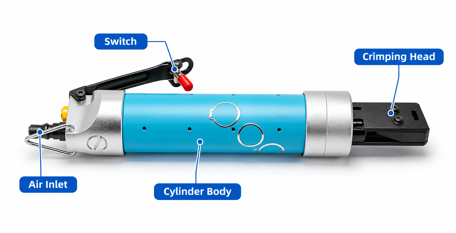
 Tool components
The tool comprises a pincer head, air cylinder, trigger lever, and air inlet. Verify the model from the laser marking on the rear cap and connect the air supply to the corresponding specification. The jaws apply force squarely to both sides of the ear base. Check jaw profile, ear dimensions, and tool approach when selecting the head.
Wear safety glasses. Keep fingers clear of the jaws and crimping area. Keep the tool pointed at the workpiece and away from people.
Before changing the pincer head, clearing a jam or servicing the tool, shut off and isolate the air supply. Bleed residual pressure, verify depressurization, then disconnect the air hose. If the tool leaks, makes unusual noises or operates abnormally, stop work and isolate the air supply.
Operating air pressure: Do not exceed the specified pressure limits.
| Parameter | TM3000 | TM5000 | TM7000 |
| Clamp band size (width × thickness), mm | 5 × 0.55 7 × 0.6 9 × 0.6 |
7 × 0.8 9 × 0.8 10 × 0.8 |
9 × 0.8 10 × 0.8 10 × 1.0 |
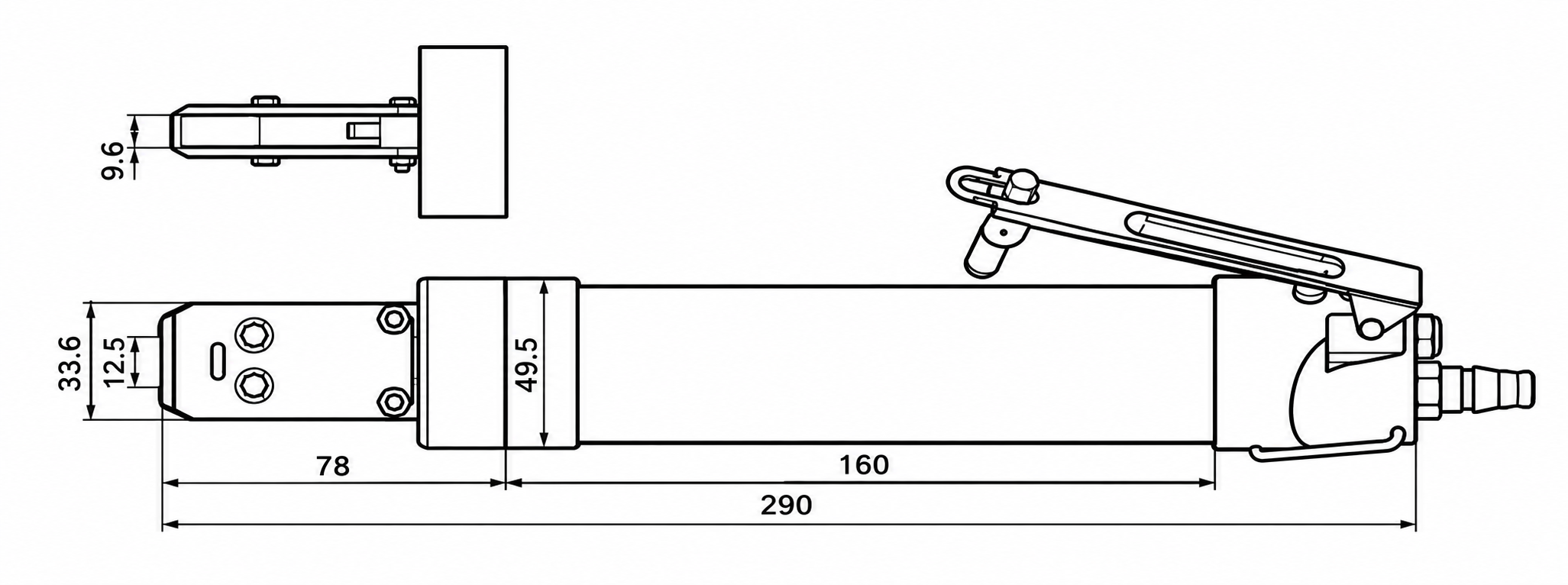
| Pincer head dimensions, mm | 12.5 × 9.6 | 16 × 10.3 | 16 × 10.3 |
| Closing force, N | 3,000 | 5,000 | 7,000 |
| Air inlet size, in | 1/4 | 1/4 | 1/4 |
| Air hose ID, mm | 10 | 10 | 10 |
| Air consumption, L | 0.3 | 0.8 | 1.1 |
| Net weight, g | 806 | 1,373 | 1,577 |
| Tool length, mm | 316 | 334 | 434 |
| Operating air pressure, bar | 3–4 | 5.5–6 | 6–7 |
| Force tolerance, N | ±85 | ±105 | ±125 |
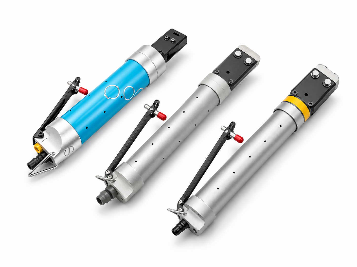
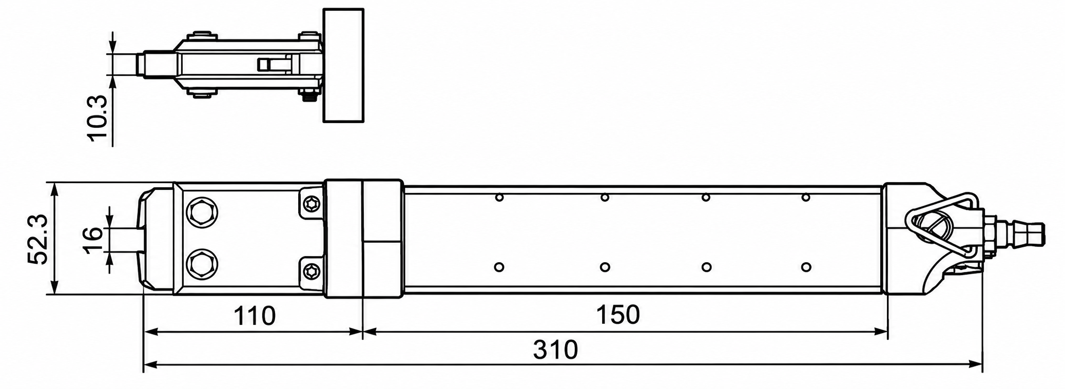
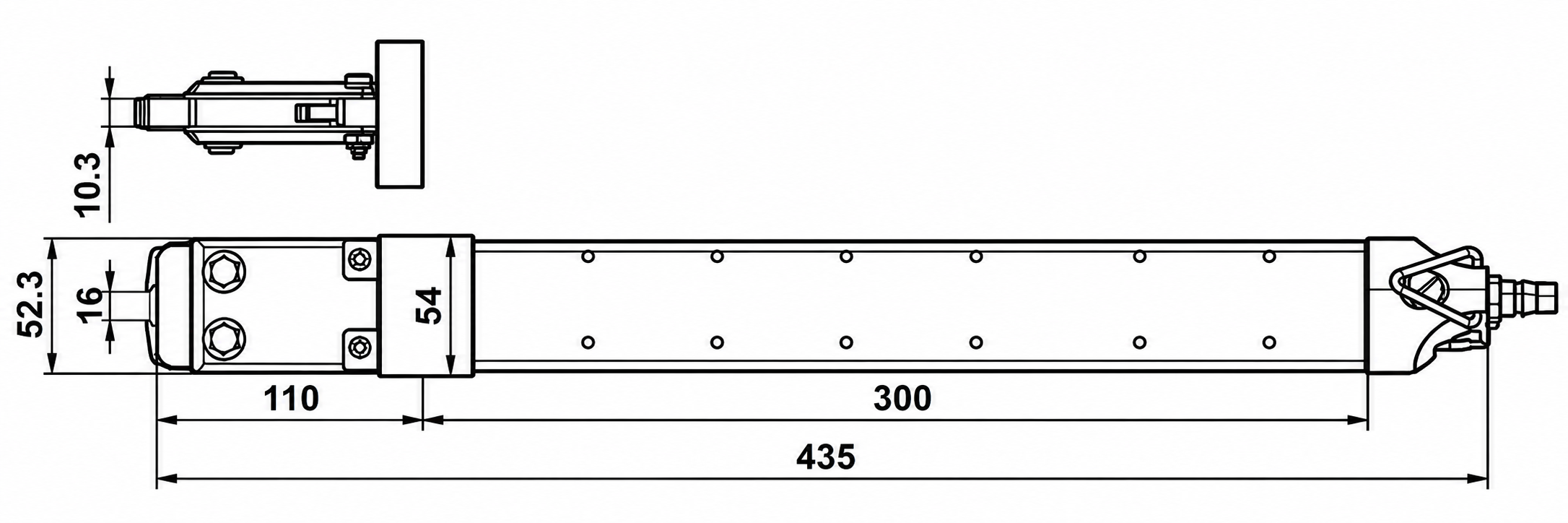
The photographs below show each model of pneumatic ear clamp pincers. Refer to the model specification table for technical data and dimensions.
| TM3000 outline and dimensions | 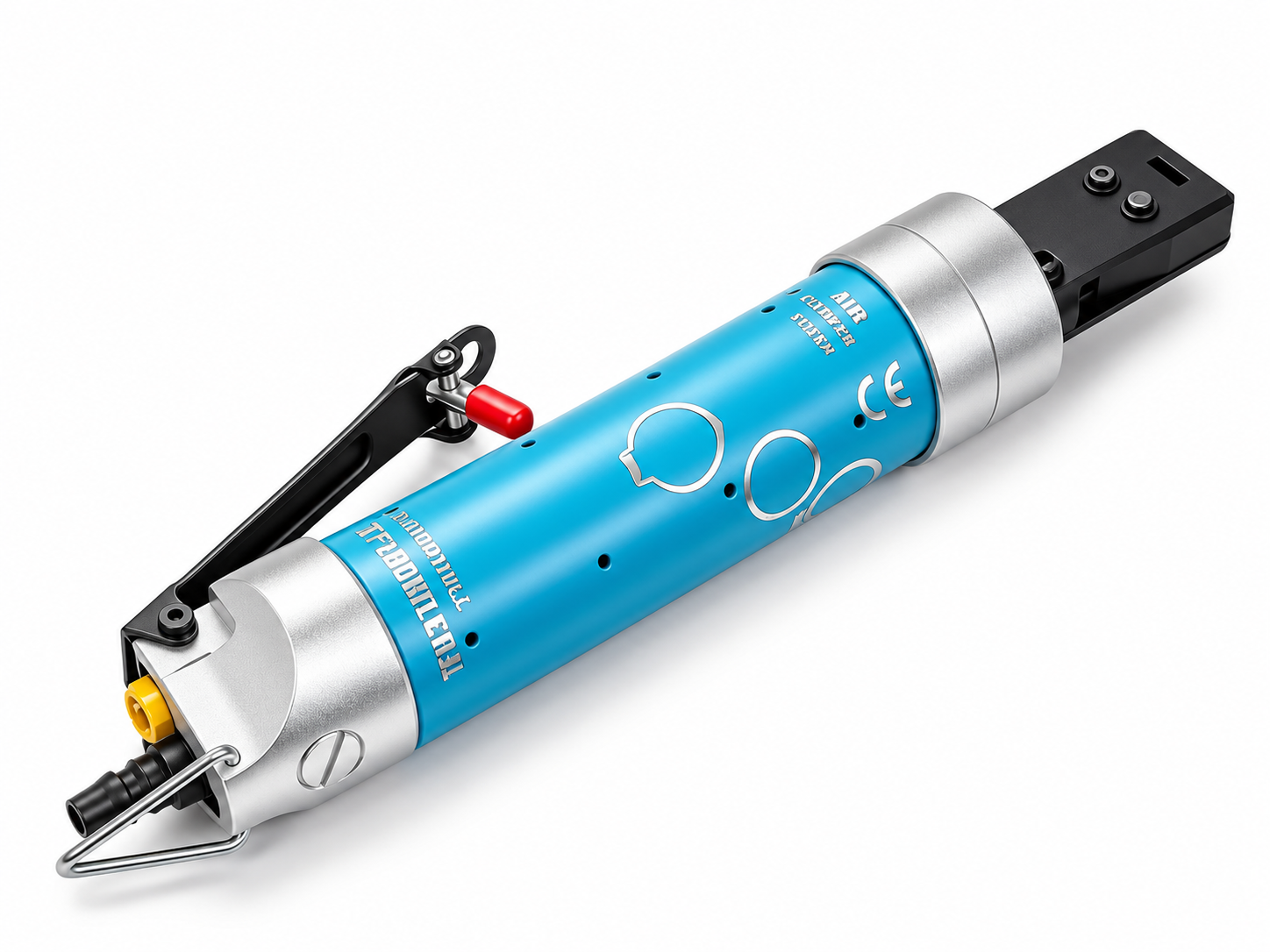 |
 |
| TM5000 outline and dimensions |  |
 |
| TM7000 outline and dimensions |  |
 |
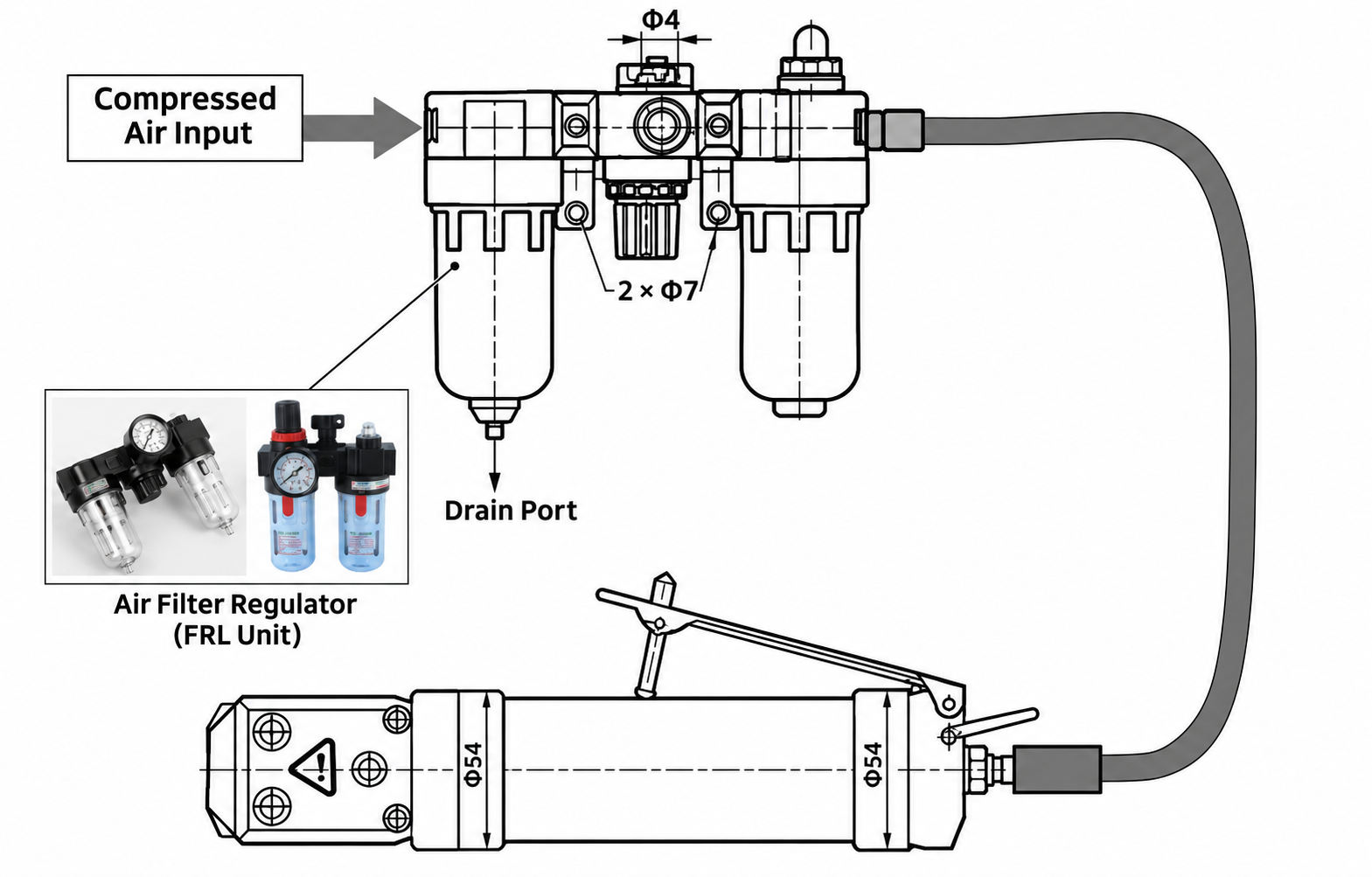 Air preparation and hose routing
Check the filter, regulator and lubricator (FRL) assembly. Drain condensate from the filter and replenish the lubricator with pneumatic tool oil as needed, following the component instructions.
With the tool disconnected and depressurized, fit the correct pincer head. Check the jaws for cracks, excessive wear and binding, and verify that fasteners are secure. Inspect the hose and fittings for damage and make sure the connections are secure.
Connect the air supply and slowly adjust the regulator within the operating range specified for the model in the table. Cycle the jaws without a clamp two or three times to check for smooth movement, proper return and air leaks.
Before production, trial-crimp a new sample clamp of the same specification on a representative assembly. Inspect the result against the process requirements. Verify closing force with a dedicated tester where required.
 |
 |
 |
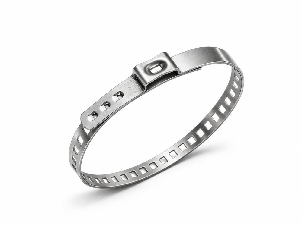 |
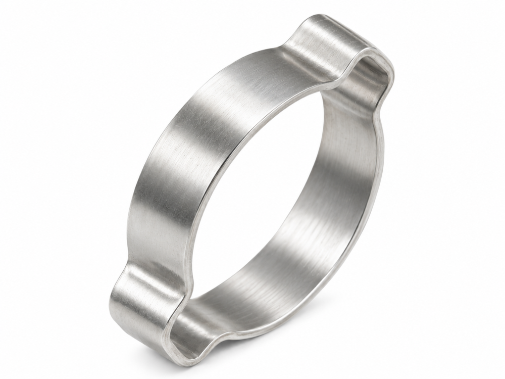
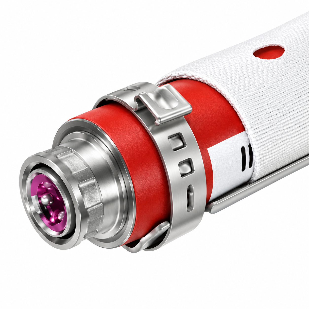
Ear clamp examples
These examples illustrate clamp designs. Confirm compatibility against the clamp specification, pincer head configuration and crimp requirements.
Each shift. Isolate and depressurize the tool before removing metal debris from the jaws. Inspect the hose and fittings and drain the filter in accordance with the component instructions.
Periodic maintenance. Inspect the pincer head for wear and check the retaining screws. Before extended storage, clean the tool and apply corrosion protection to exposed metal surfaces as specified.
| Symptom | Possible cause | Corrective action |
| No cycle or weak closure | Low supply pressure or an air leak | Check the hose, fittings and regulator. Set the pressure within the verified range. |
| Incomplete crimp or loose clamp | Low pressure, worn head or clamp misalignment | Check the pressure and alignment. Replace the head if needed, then retest with a new clamp. |
| Clamp cracks during crimping | Excessive pressure or incorrect head | Segregate affected assemblies. Confirm the head and settings, then retest with a new clamp. |
| Jaws bind | Debris or insufficient lubrication | Isolate and depressurize before cleaning. Check lubrication per the FRL instructions. Remove from service if binding persists. |
Do not modify the tool. Use a compatible original pincer head. For warranty coverage involving non-original heads, refer to TFURTHER’s warranty terms.
Provide the tool model, clamp type, band width and thickness, clamp size range, required pincer head, working clearance, and quantity. Specify the control configuration if foot operation is required. Confirm closing force, air pressure, and head compatibility against the tool specification and approved assembly process.
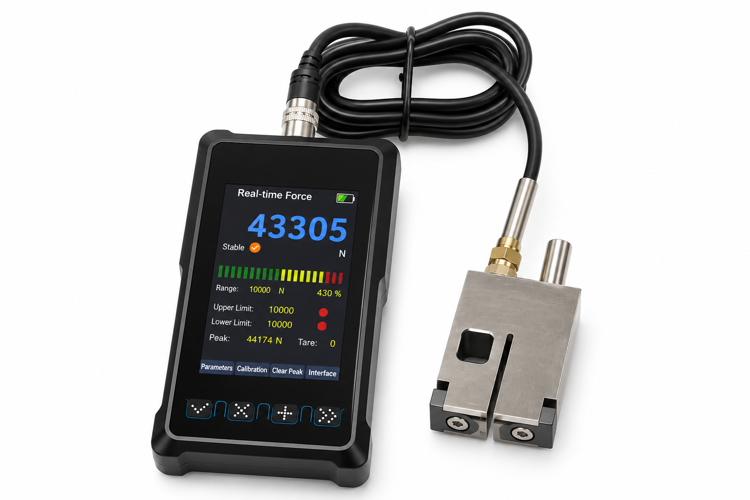
Supply pressure fluctuations, pincer head wear and changes in setup can affect actual closing force. Use a dedicated force tester with current third-party calibration and verify closing force at the intervals specified by the site process.
Record the tool model, pincer head, supply pressure and measured force. Evaluate the results against the approved force window. Suspend use if the result falls outside that window, then troubleshoot and retest. Closing force is the force applied by the tool. Verify assembly performance against the applicable inspection requirements.
 |
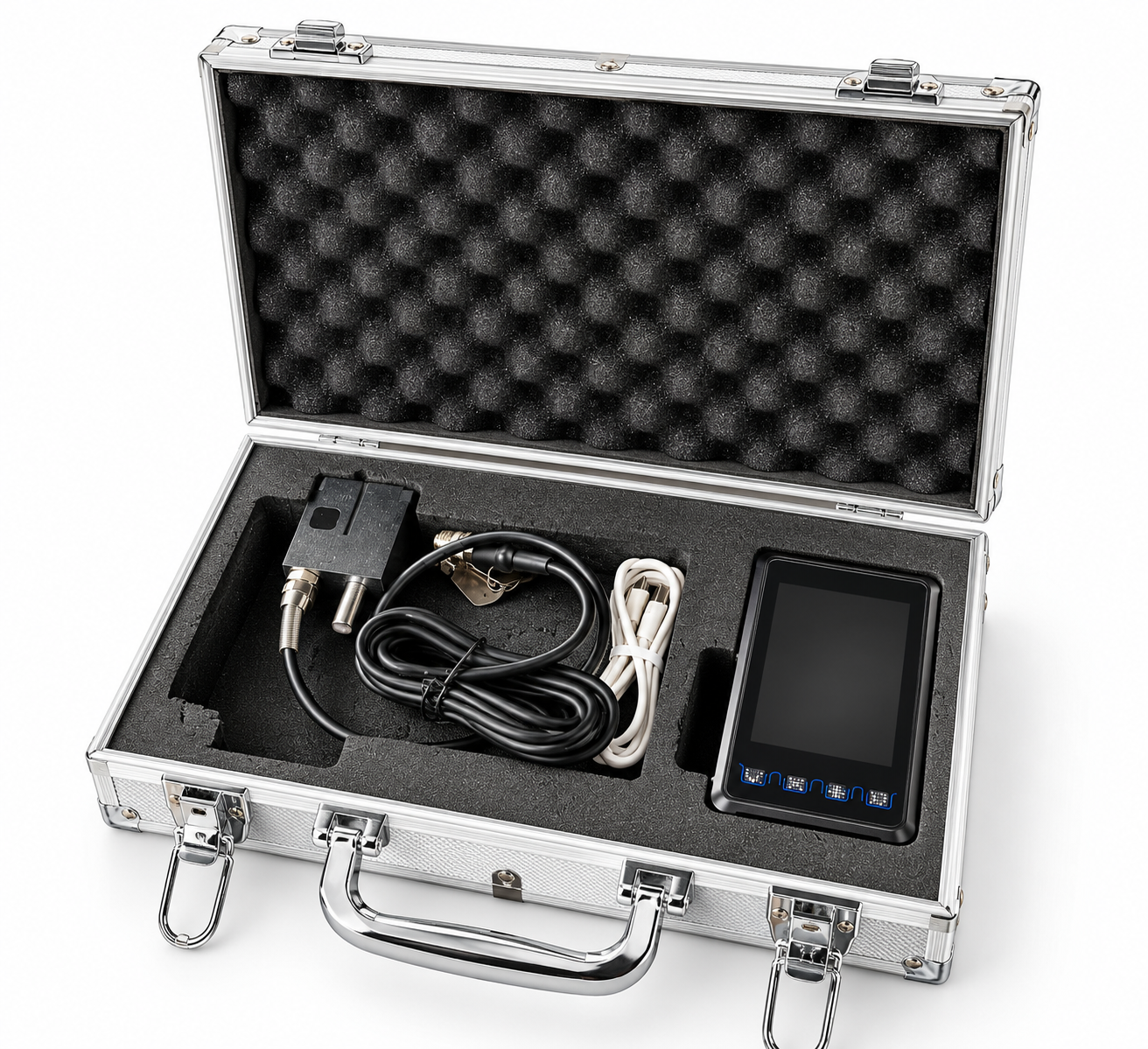 |
Force tester and kit
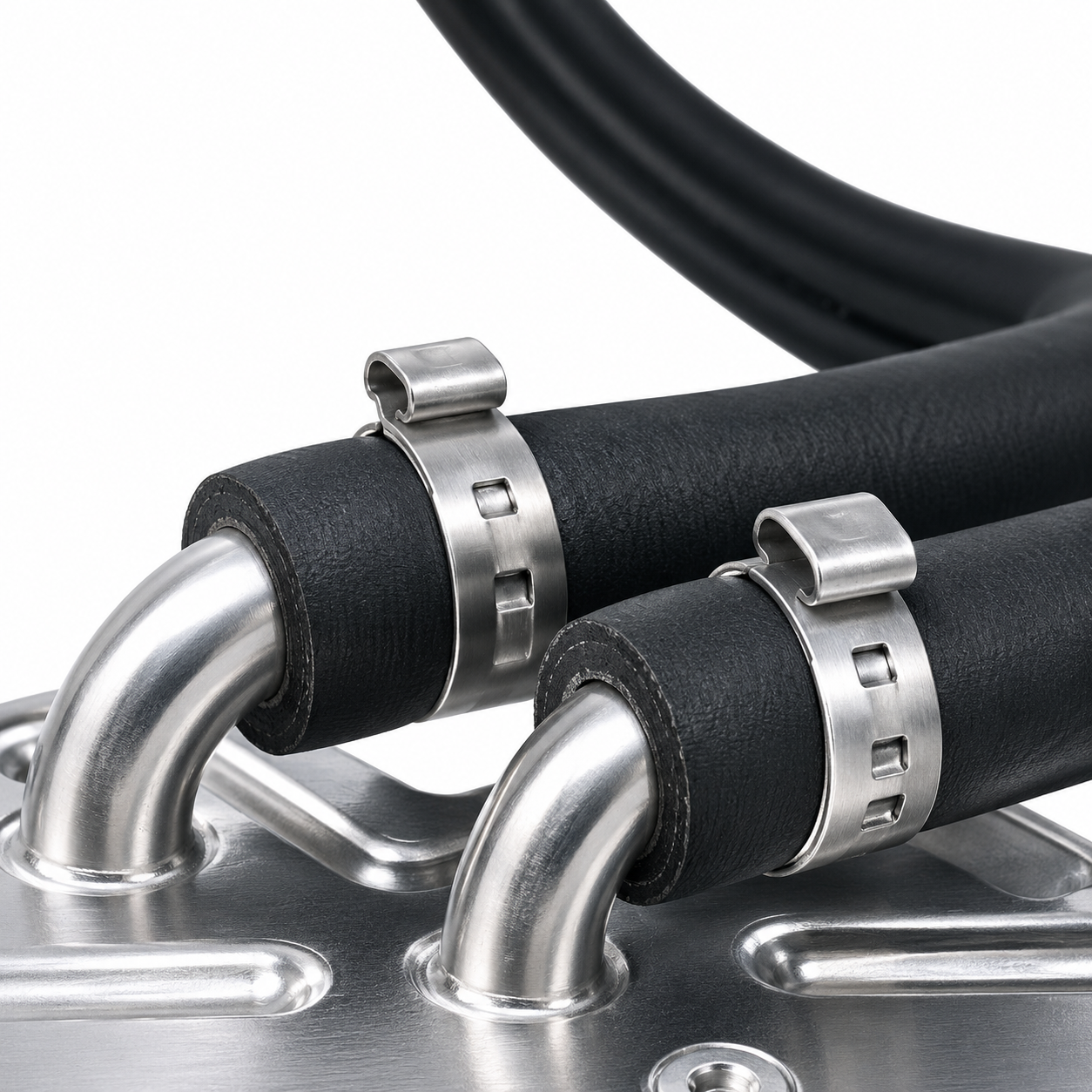
Clamp assembly examples