

Welded crimp ring. The stainless steel ring is formed and closed by welding. The part drawing specifies the seam design and location. After crimping, inspect the seam and surrounding area against the acceptance criteria.
Seamless crimp ring. The ring is cut as a single piece with a continuous circumference and no welded joint. Check the cut edges for burrs, sharp edges and nicks that could score the hose during placement or crimping.
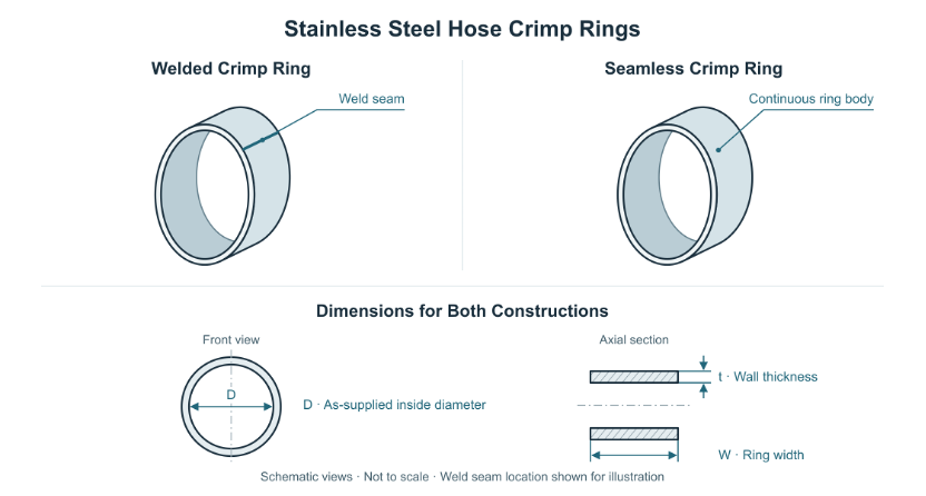 Figure 1 Welded and Seamless Ring Designs and Dimension Symbols
Both constructions use stainless steel. In Figure 1, D is the as-supplied inside diameter, W is the axial ring width, and t is the wall thickness. Refer to the approved part drawing for the material grade, dimensional tolerances and surface requirements.
| W(mm) Ring Width |
t(mm) Wall Thickness |
Series Diameter Range(mm) |
| 7 | 0.8 | 15–40 |
| 7 | 1.0 | 19–80 |
| 8 | 0.8 | 15–50 |
| 8 | 1.0 | 19–80 |
| 10 | 0.8 | 15–80 |
The table lists series diameter ranges by ring width W and wall thickness t. When ordering, use the specific Towin part number and approved drawing to confirm ring construction, available sizes, the diameter measurement condition, and tolerances.
Seat the hose on the fitting to the specified insertion depth. Determine the minimum and maximum assembled hose outside diameters at the clamping zone. Select an as-supplied ring size that clears the slide-on path and check that the required diameter reduction is within the limit for that construction.
Use trial assemblies to establish the target crimp dimension and acceptance tolerance, taking into account hose wall thickness, hardness, fitting geometry and service conditions. Confirm the allowable diameter reduction for each construction separately using drawings and trial assemblies. Validate the process at both assembly diameter limits. Check retention or sealing at the lower limit and the risk of excessive compression at the upper limit.
Select the matched dies for the ring construction, size and target crimp dimension. Slide the ring onto the hose before fitting assembly. Seat the hose on the fitting, then position the ring in the specified clamping zone. Align it with the assembly axis and center it in the dies.
Crimp the ring using the validated force or stroke setting. Crimping force is the force applied by the tooling during installation. Radial clamping force is the load the installed ring applies to the joint. Confirm the process setting by checking the installed dimensions and testing the complete assembly.
After releasing the dies, check the crimp outside diameter at the specified measurement location. Check roundness, axial ring position and the hose surface for scoring or abnormal indentations. For welded rings, also check seam integrity. For seamless rings, inspect the ring body and cut edges for cracks or damage. Follow the approved procedure for any nonconforming assembly.
Verify leak tightness or axial pull-off force on the complete assembly as required by the application. If the ring construction, material condition, hose, fitting or dies change, review the existing crimp settings and inspection limits for the new configuration.
For a quote, specify the ring construction, existing part number or drawing, material grade, as-supplied inside diameter D, ring width W, wall thickness t, target installed dimension and quantity. For a new application, include hose and fitting drawings, service medium, temperature, operating pressure and any leak or pull-off acceptance requirements.