

The mechanical interlock joins the band ends. A tongue seats in the groove to provide a smooth transition at the overlap. Closing the ear reduces the band diameter and compresses the hose against the fitting.
| Series | Band material | Width × thickness (mm) | Inside ear width (mm) | Series size span (mm) |
| TF01A | Stainless steel | 5 × 0.55 | 4, 5.5 | 5.3–11.8 |
| TF01B | Galvanized steel | 7 × 0.8 | 8 | 9.4–17.5 |
| TF01D | Stainless steel | 7 × 0.6 | 8, 10 | 9.4–120.5 |
| TF01E | Stainless steel | 7 × 0.8 | 10.7 | 14.6–120.5 |
| TF01F | Stainless steel | 7 × 0.6 | 10.7 | 15.1–75.0 |
Each series span covers the listed part sizes. Confirm the size range and inside ear width for the specific Towin part number.
Seat the hose to the specified depth and measure the assembly outside diameter (OD) at the clamping location. Consider OD tolerances, hose wall thickness and hardness, fitting support and installation space. If several sizes fit, trial them at both OD limits and check clearance for fitting the clamp, tool access and the condition after crimping.
Position and engage the clamp. Place the clamp at the specified clamping location. Check that the band sits flat and the interlock is fully engaged. Allow end access for axial fitting. Install radially from the side only if the interlock design for the selected part allows it.
Align the jaws and crimp. Use a pincer head matched to the clamp. Align the jaws at the base of the ear and crimp in a single stroke at the validated closing force. Base the force setting on the required hose compression, hose hardness and fitting support. Closing force is the load applied by the jaws during crimping. Verify retention or sealing on the complete assembly.
Figure 1 identifies the initial inside ear width as s and the residual ear gap after crimping as s′. With force-controlled crimping, the residual gap can vary with assembly size. Dividing the initial ear width by pi gives a rough theoretical upper limit for diameter reduction. Confirm actual reduction and ear-gap limits through trial assemblies.
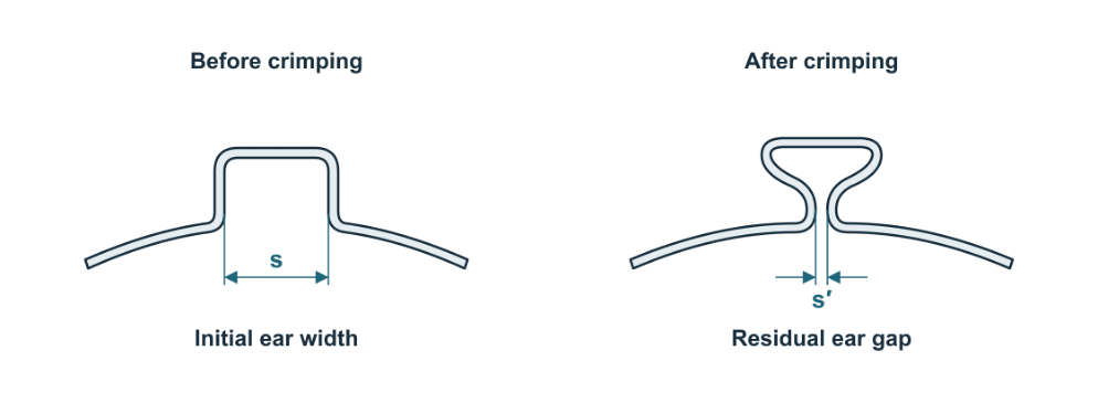 Figure 1 Initial Inside Ear Width and Residual Ear Gap
Block closure occurs when the ear legs contact at the base before the joint reaches the required compression. The contact takes up most of the additional jaw load and limits further tightening. Allow the ear height to form during crimping and avoid using a stop or manually adjusting the gap. If the crimp falls outside the acceptance limits, follow the approved rework procedure.
If the clamp rotates with the assembly, check the installed rotational envelope diameter (RD) about the actual axis of rotation. Determine it from the outermost point of the clamp relative to that axis, including protrusions such as the crimped ear and interlock. Check minimum running clearance to adjacent components across the assembly tolerances, allowing for radial runout.
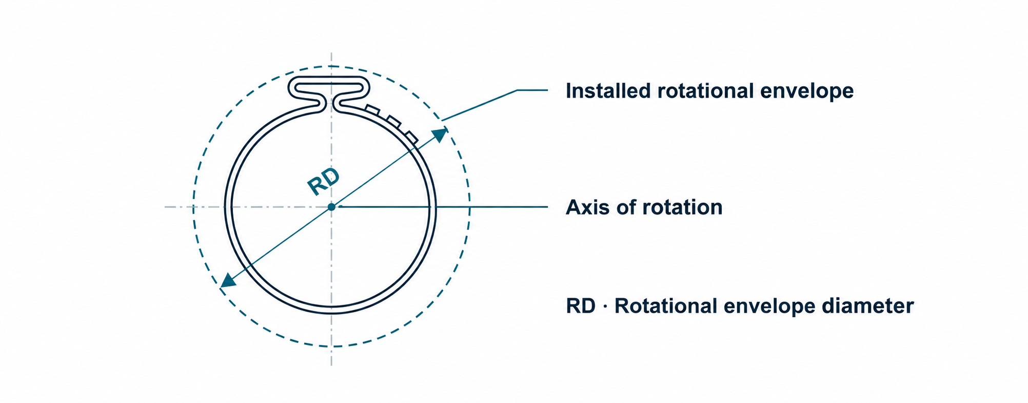 Figure 2 Installed Rotational Envelope Diameter RD
Inspect clamp position, interlock engagement, residual ear gap and hose surface condition. Verify sealing or axial pull-off performance at both assembly OD limits as required by the application. Where process traceability is required, record the part number, tool setting, measured closing force, closure displacement and inspection results in accordance with the control plan.
Specify the Towin part number, band material or finish, band width and thickness, assembly OD limits and quantity. For new applications, include hose and fitting drawings or samples. For rotating assemblies, also provide the available installed envelope and maximum operating speed.